Bu makalede, sabit koniyle birlikte çalışarak salınımlı hareketle malzemeleri ezen bir çekirdek kırma bileşeni olan koni kırıcı başlığı ayrıntılı olarak açıklanmakta ve bu başlığın performansı doğrudan verimi, ürün granülaritesini ve aşınma direncini etkilemektedir. Başlık gövdesi (çekirdek yapısı), aşınma astarı (manto), yatak deliği, montaj özellikleri ve havalandırma/ağırlık azaltma boşlukları dahil olmak üzere bileşimi, yapısal özellikleriyle birlikte özetlenmektedir. Başlık gövdesinin döküm süreci, malzeme seçimi (dökme çelik veya sünek demir), kalıp yapımı, kalıplama, eritme, dökme, ısıl işlem ve muayeneyi kapsayacak şekilde ayrıntılı olarak açıklanmaktadır. Ayrıca, başlık gövdesinin ve aşınma astarının işlenmesi ve montaj adımları da açıklanmaktadır. Ayrıca, malzeme testi, boyutsal doğruluk kontrolleri, aşınma direnci testi, montaj ve performans testi ve tahribatsız muayene gibi kalite kontrol önlemleri de belirtilmektedir. Bu işlemler, başlığın yüksek mukavemete, aşınma direncine ve boyutsal doğruluğa sahip olmasını sağlayarak ağır kırma işlemlerinde güvenilir performans sağlar.
Detailed Introduction to the Cone Crusher Head Component
1. Function and Role of the Cone Crusher Head
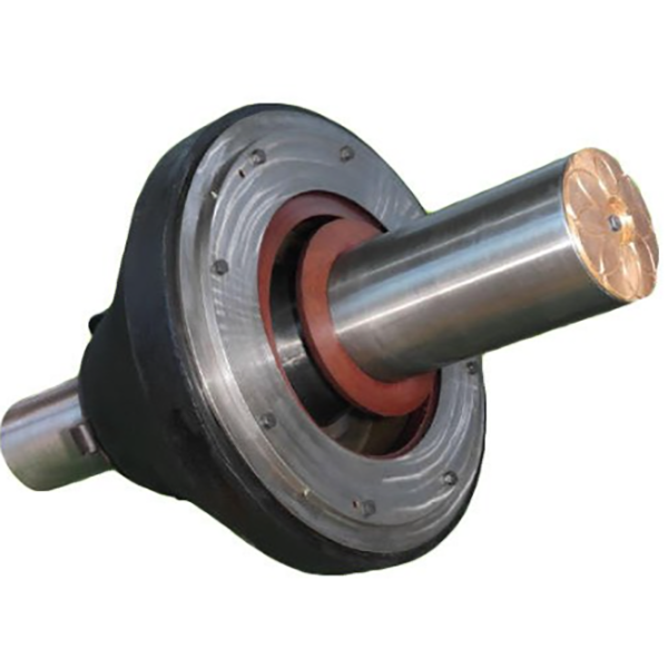
The cone crusher head (also known as the moving cone or 破碎锥) is the core crushing component that directly contacts and crushes materials. It works in conjunction with the fixed cone (bowl liner) to form a crushing chamber, and its oscillating motion (driven by the eccentric shaft) compresses and crushes rocks, ores, and other bulk materials. The head’s shape, surface hardness, and structural strength directly determine the crusher’s throughput, product granularity, and wear resistance. Under high-pressure working conditions, it must withstand intense impact and friction, making it one of the most critical wear parts in the equipment.
2. Composition and Structure of the Cone Crusher Head
The cone crusher head is a composite structure combining a cast iron or steel body with a wear-resistant liner. Its main components and structural features include:
Head Body (Core Structure): A conical or frustoconical casting made of high-strength cast steel (e.g., ZG35CrMo) or ductile iron (QT600-3). It serves as the structural support for the wear liner and connects to the eccentric shaft via a central bore. The body’s inner cavity is designed to fit the eccentric bushing, with keyways or bolts to secure the connection and transmit torque.
Wear Liner (Mantle): A replaceable outer layer made of high-chromium cast iron (Cr20-Cr26) or alloy steel with high hardness (HRC 55-65). It is attached to the head body via bolts, dovetail grooves, or wedge blocks, ensuring tight fitting to prevent movement during crushing. The liner’s surface is often designed with a concave or convex profile (e.g., standard, coarse, or fine crushing profiles) to optimize material gripping and crushing efficiency.
Bearing Bore: A central cylindrical or tapered hole in the head body that accommodates the upper end of the eccentric shaft. The bore is precision-machined to ensure a stable fit with the shaft, with lubrication channels drilled to deliver oil to the contact surface, reducing friction and wear.
Mounting Flange or Bolt Holes: Located at the base of the head body, these features secure the wear liner to the body. Dovetail grooves on the liner’s inner surface mate with corresponding protrusions on the head body, enhancing connection strength under impact loads.
Ventilation and Weight Reduction Cavities: Some large-sized heads have internal hollow structures to reduce weight, improve heat dissipation, and avoid excessive inertia during oscillation. These cavities are designed to not compromise the body’s structural integrity.
3. Casting Process for the Head Body
The head body is primarily manufactured using sand casting or lost foam casting due to its large size and complex shape. The process steps are as follows:
Material Selection:
Cast steel (ZG35CrMo) is preferred for large crushers due to its high tensile strength (≥785 MPa) and impact toughness, suitable for heavy-duty crushing.
Ductile iron (QT600-3) is used for medium-sized heads, offering good castability and cost-effectiveness while maintaining sufficient strength.
Pattern Making:
A full-scale pattern is created using wood, foam, or 3D-printed materials, replicating the head’s external shape, internal cavity, and mounting features. For lost foam casting, the foam pattern includes integrated runners and risers.
Shrinkage allowances (2-3% for cast steel) and draft angles (3-5°) are added to compensate for post-casting contraction and facilitate pattern removal.
Molding:
For sand casting: Resin-bonded sand is packed around the pattern to form the mold cavity, with a sand core inserted to create the central bore and internal cavities. The mold is cured to ensure hardness and dimensional stability.
For lost foam casting: The foam pattern is coated with a refractory slurry (ceramic or zirconium-based) to form a 3-5 mm thick shell, then embedded in dry sand.
Melting and Pouring:
Cast steel is melted in an electric arc furnace at 1500-1600°C, with alloying elements (Cr, Mo) added to achieve the required chemical composition. The molten metal is deoxidized and desulfurized to reduce impurities.
Pouring is performed at a controlled rate (50-100 kg/s for large heads) to avoid turbulence and ensure complete filling of the mold. For lost foam casting, the molten metal vaporizes the foam pattern, replacing it in the mold cavity.
Cooling and Cleaning:
The casting is allowed to cool slowly (over 24-48 hours) to prevent thermal cracking, then removed from the mold. Sand or refractory material is cleaned via shot blasting or water jetting.
Risers and gating systems are cut off, and rough edges are ground to prepare for machining.
Heat Treatment:
Cast steel heads undergo normalization (850-900°C, air-cooled) to refine grain structure, followed by quenching and tempering (600-650°C) to achieve hardness of 220-260 HBW, balancing strength and machinability.
Ductile iron heads are subjected to annealing (900-950°C) to eliminate carbides and improve toughness.
Casting Inspection:
Surface defects (cracks, pores, shrinkage) are checked via visual inspection and dye penetrant testing (DPT).
Internal flaws are detected using ultrasonic testing (UT) and magnetic particle testing (MPT), with strict standards (no defects larger than φ3 mm in critical load-bearing areas).
4. Machining and Manufacturing Process
Head Body Machining:
Rough Machining: CNC lathes or boring machines are used to rough-turn the outer surface, base flange, and central bore, leaving 2-3 mm finishing allowance. Keyways and bolt holes are pre-drilled and tapped.
Heat Treatment: Stress relief annealing (550-600°C) is performed after rough machining to eliminate residual stresses from casting and initial cutting.
Finish Machining: Orta delik, eksantrik şafta sıkı bir şekilde oturmasını sağlamak için Ra1,6-3,2 μm yüzey pürüzlülüğüne sahip IT7 toleransına göre hassas taşlanmıştır. Taban flanşı ve montaj yüzeyleri, astarın güvenli bir şekilde sabitlenmesi için düzlük (≤0,1 mm/m) elde etmek üzere frezelenmiştir.
Aşınma Astarı Üretimi:
Döküm: Yüksek kromlu dökme demir gömlekler, sertliği ve aşınma direncini artırmak için alaşım elementleri (Cr, Mo, Ni) eklenmiş kum döküm yöntemiyle üretilir. Döküm, HRC 55-65'e ulaşmak için söndürme ve temperleme işlemlerine tabi tutulur.
İşleme: Astarın iç yüzeyi (kafa gövdesiyle birleşen), kırlangıç kuyruğu oluklarına veya cıvata deliklerine uyacak şekilde işlenerek sıkı bir bağlantı sağlanır. Dış kırma yüzeyi, döküm çapaklarını gidermek ve tasarlanan profili elde etmek için taşlanır veya parlatılır.
Toplantı:
Aşınma astarı, gevşemeyi önlemek için torkun eşit olarak (boyuta bağlı olarak 200-500 N·m) uygulanmasıyla yüksek mukavemetli cıvatalar (8.8 veya 10.9 sınıfı) veya kama blokları kullanılarak kafa gövdesine monte edilir.
Astar ile gövde arasına, iki bileşen arasında aşınmaya neden olabilecek malzeme girişini önlemek için contalar veya sızdırmazlık maddeleri uygulanır.
5. Kalite Kontrol Süreçleri
Malzeme Testi:
Kimyasal bileşim analizi (spektrometri yoluyla), dökme çeliğin/demirin alaşım standartlarını karşıladığından emin olunmasını sağlar (örneğin, ZG35CrMo: C %0,32-0,40, Cr %0,8-1,1, Mo %0,15-0,25).
Her döküm partisinden alınan test kuponları üzerinde mekanik özellik testleri (çekme dayanımı, darbe tokluğu, sertlik) yapılır.
Boyutsal Doğruluk Kontrolleri:
Koordinat Ölçüm Makineleri (CMM), kafa gövdesinin dış çapını, delik boyutunu ve gömlek profilini doğrulayarak tasarım çizimlerine uygunluğu sağlar (kritik boyutlar için tolerans ±0,5 mm).
Salınım sırasında dengesizliği önlemek için baş gövdesinin dış yüzeyi ile merkezi delik arasındaki eş merkezlilik ölçülür ve ≤0,05 mm/m gereklidir.
Aşınma Direnci Testi:
Aşınma astarı numuneleri, standartlaştırılmış koşullar altında ağırlık kaybını ölçmek için aşındırıcı aşınma testine (örneğin, ASTM G65) tabi tutulur ve nominal yük altında aşınma oranının ≤0,1 g/saat olması sağlanır.
HRC 55-65'i doğrulamak için astar yüzeylerinde sertlik testi (Rockwell C ölçeği) yapılır ve yumuşak noktalara (≤HRC 50) izin verilmez.
Montaj ve Performans Testi:
Liner uyum testleri, liner ile baş gövdesi arasında boşluk olmadığından emin olunmasını sağlar (maksimum boşluk ≤0,1 mm olacak şekilde kalınlık ölçerlerle kontrol edilir).
Montajı yapılmış kafa üzerinde dinamik denge testi yapılarak, çalışma hızında titreşim genliğinin ≤0,1 mm/s olması sağlanarak eksantrik şaft üzerindeki stres azaltılır.
Tahribatsız Muayene (NDT):
İşleme sonrasında kafa gövdesi UT ve MPT ile tekrar kontrol edilerek, işleme sırasında oluşan çatlaklar tespit edilir.
Liner yüzeyleri görsel muayene ve DPT yoluyla döküm kusurları (gözeneklilik, çatlaklar) açısından kontrol edilir, kusurlu linerler reddedilir veya onarılır.
Bu döküm, işleme ve kalite kontrol süreçlerine bağlı kalınarak konik kırıcı kafası yüksek mukavemet, aşınma direnci ve boyutsal doğruluk elde eder ve sürekli, ağır hizmet tipi kırma işlemlerinde güvenilir performans sağlar.